HOME Flying Quotes Paragliding Addictionary Whether to Fly DIY Electronics for PG Sites Logged Gallery A Diary Contact
Total Cost ~ US$75
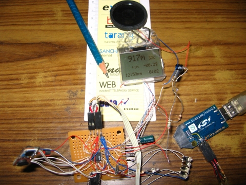
There's a big market for spare LCD displays for Nokia cellphones, and replacements for the Nokia 3310 LCD are very inexpensive and readily available (US$4 in India!). The LCD has an easy to program 4 pin gpio interface, and requires less than 1 mA at 3V.
Flight log data is saved to a page of flash (512 bytes) on the 8051F320 MCU. Up to 30 flight records are saved, if there are more than 30 flights, the oldest one is erased to make room for the new record. I needed a few bytes of non-flash memory to store a few more software parameters. Ideally I should have used the DS1338C-3.0 Real-Time Clock. This chip has 56 bytes of available RAM. But unfortunately, I didn't have the part and had to make do with a DS1337C. So I used a salvaged 24LC02 256byte serial EEPROM for the additional non-volatile memory.
Update: Since I've received a lot of questions about making the change, here's what you need to
do :
1. Replace the 24LC02 i2c device id (0xA0) with the DS1338C device id (0xD0)
2. The 56 bytes of available RAM on the DS1338C start at byte address 0x08, not 0x00
The
zip file contains the changes. I haven't tested this myself, but I've received feedback that
its OK.
I used the Silicon labs ToolStick USB Programming base adapter to flash the MCU. This costs about USD17.50. I'd already purchased one for my earlier vario project using a Silabs F330 Toolstick. I soldered the C2 programming interface connections to a 0.1" 6-pin header and glued the header to the side of the USB adapter.
Update: Lots of questions about this, so here are the details.
An even cheaper programming option is the Silicon Labs 'Toolstick Evaluation Kit' for USD10.99. Cut the board between the USB programmer chip and the target chip, connect your own cable for the C2 programming interface and you have a really cheap USB flash programming adapter for the full range of Silicon Labs MCUs.
For audio output, I used a sensitive 16ohm mini-speaker. I tried some salvaged 32ohm headphone and cellphone units, but they were not loud enough. If you have a sensitive broad-band piezo transducer (freq range ~ 1kHz to 4kHz) you can get rid of the speaker, 200ohm resistor, 100uF cap and BSS138 FET transistor. Connect the piezo beeper directly to the mcu pin. This should more than double the battery life.
Update: the Kingsgate KPEG006 piezo works very well, frequency range 200Hz to 5kHz. One source is RS Electronics.
After profiling the code, I managed to reduce the mcu clock to 1.5MHz. This resulted in an idle current consumption of less than 2mA, increasing to about 16mA when the audio tone is being generated. There is no on-off switch - you "power-down" by navigating to the flight log display page and pressing the Select button. The mcu then powers down the LCD display, switches to the 32kHz clock generated by the DS1337 RTC, and shuts down the internal clock oscillator. In this low-power sleep mode, the total circuit current consumption is just 0.4mA !!
To power up from sleep mode, press the Select button for about 5 seconds.
The circuit operates at 3V. To avoid switching noise from a charge-pump voltage regulator, I used a Lithium Polymer battery and an LX8211 low-dropout (150mV) 3V linear regulator. LiPoly batteries have a voltage of 4.2V when fully charged, with a nominal voltage of 3.7V.
I used a standard Nokia cellphone BL-5C LiPoly battery. Battery life was well over 100 hours the one time I left it to run in flight display mode with the audio tone being generated approximately 25% of the time.
Update: Someone pointed out correctly, that this circuit does not provide over-discharge protection even though it it is drawing power continuously even in sleep mode. So it would be a good idea to use LiPoly batteries that have inbuilt protection (thats over-charge and over-discharge protection) circuits. The TrustFire range of Li-Ion batteries with 900mAH capacity have built-in protection, come in AA form factor, stick them in a AA battery holder and you're done. You can build your own customized USB or mains adapter battery charger with a bare minimum of components using specialized LiPoly charger ICs - e.g. the MAX1555 or MAX8600.
The code archive contains the source code and Silicon Labs configuration wizard and IDE project files. Last update : 2008 November 16
On power up, the flight log is displayed. Each flight record consists of the flight number, flight date, flight launch time, flight duration, launch altitude, maximum altitude, lz altitude, maximum climb rate,maximum sink rate, maximum temperature and minimum temperature. Use the L and R buttons to cycle through the 30 flight records. Flight 01 is the most recent flight, flight 30 is the oldest flight. Press the Select button to power down. Press the Page button to move to the Settings page. Press both the Select and Page button simultaneously to clear the flight log.
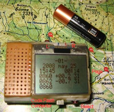
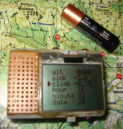
In the Settings page, press the Select button to cycle through the different options, and the L and R buttons to change the parameter values.
You can correct the altitude to some extent by selecting one of three pressure-altitude tables. They differ in the value of the mean sea level pressure used as a reference in computing altitude above mean sea level. Select the middle table for Airspace (aka Pressure or Flight) altitude. This uses a nominal mean sea level pressure of 1013.25mBar.
The sink rate threshold for the audio sink warning can be adjusted from -1.0m/s to -4.0m/s in steps of 0.5m/s.
Modern paragliders have a minimum sink rate of about -1.0m/s, so if you are sinking slower than this, you are in lifting air. The climb rate threshold for audio lift indication can be adjusted from -0.75m/s to 0.0m/s in steps of 0.25m/s.
The other settings are for the real-time clock calendar date and time.
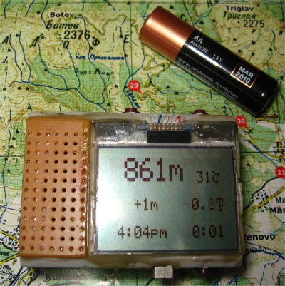
Press the Page button to select the flight display mode. In this mode, the screen displays the altitude in metres above sea level (MSL), temperature in degrees Celsius, altitude above launch in metres, climb rate in m/s, current time, and elapsed flight time in hours and minutes.
When you enter this mode, the climbrate audio threshold is set to 0.0m/s so you can check the variometer function is working correctly.
When you are ready to launch, press the Select button to record the launch altitude. An "OK" status is then displayed on the screen. The climbrate computation is now disabled to avoid the distraction of a noisy vario while you are waiting to launch.
After you launch, when the altimeter sees an elevation change of 5m from the recorded launch altitude, the flight duration timer display automatically starts. And of course, the climbrate calculation will then be enabled, and the climbrate threshold for the audio beep is set to the value you specified in the Settings page.
After landing, press the Page button. The unit will now record the landing altitude, and then display the completed flight statistics. To power down, press the Select button. Else press the Page button to move to the Settings page.