HOME Flying Quotes Paragliding Addictionary Whether to Fly DIY Electronics for PG Sites Logged Gallery A Diary Contact
Inertial motion estimation software computes gravity compensated earth Z axis acceleration data. Kalman filter uses acceleration data plus pressure sensor data to estimate altitude and climbrate.
Works very well indeed, AND mathematically "optimal" signal processing. Engineering nirvana ...
The Wikipedia tutorial example is the perfect match for our problem. Essentially, it attempts to track the position and velocity of a moving object that is moving linearly and perturbed by random accelerations. For us (glider pilots) that maps to tracking altitude and climb/sink rate.
However, I made a change to the way the Kalman filter update function is implemented. The software assumes a fixed acceleration noise variance, and uses pressure/altitude noise variance as a dynamic input to the update function. I figured the pressure/altitude sensor noise variance should be treated as a fixed quantity. This is easily determined offline, or during initialization of the software module. Instead, I use the acceleration variance as an input to the kalman filter update function. The acceleration perturbation of the system is what can change dramatically in a thermaling environment, and it would be great if we could get some real data for this.
I first saw a reference to computing vertical acceleration on Fabio Varesano's FreeIMU website. FreeIMU is attitude and heading reference system (AHRS) estimation software and hardware that uses a combination of 3-axis gyroscope, accelerometer and magnetometer to estimate roll, pitch (attitude) and yaw (heading).
Why not just use the Z axis data value from an accelerometer ? Well, the accelerometer can be mounted in any orientation, and is then subject to changes in orientation due to banking and pitch. So computing the AHRS parameters is required in order to compute the earth-frame vertical acceleration of the system.
My first experiments were implemented on a homebrew controller board with a Freescale K20 Cortex M4 microcontroller, MAX21000 gyro, MMA8451 accelerometer, HM5883L compass and BMA180 pressure sensors, using a ported version of FreeIMU (which is written for 8-bit AVR microcontrollers).
The acceleration data from the AHRS software, and the altitude data derived from the pressure sensors, are inputs to the Kalman filter update function.
The results were good, an improvement over using pressure sensor data alone. But using the acceleration data to provide a measure of the acceleration variance isn't as useful as using the acceleration data as a direct input to measure velocity !
So I modified the Kalman filter algorithm to explicitly use the acceleration data in estimating velocity and position. The end result is more compute-intensive (3 state parameters instead of 2) but is a better match for the available data. I am pretty happy with the implementation results. Fast and configurable response.
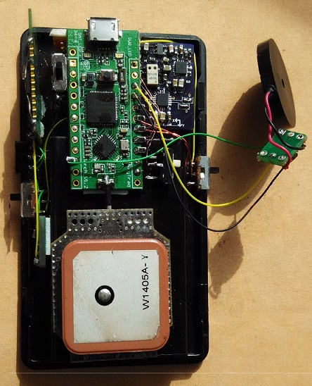
This new algorithm was implemented on a different hardware platform. I had acquired a Navspark board. This is a GPS/GLONASS breakout board with the latest Venus 8 chip. Embedded Sparc controller running at 82MHz, 1MByte of flash, 212kbytes RAM. Custom Arduino development environment, with the GPS/GLONASS code available as library. SPI, I2C, PWM, GPIO and UART interfaces.
I designed a homebrew IMU sensor board with MAX21100 gyroscope+accelerometer, HMC5883L magnetometer, and MS5611 pressure sensor. Added a 16Mb spi serial flash, BC04B slave bluetooth module, piezo speaker+driver, and Lipoly battery and charger.
The end result is a hardware dongle that can log GPS data, compute AHRS data and vertical acceleration, compute climbrate/sinkrate using the sensor fusion Kalman filter, generate acoustic vario feedback, and transmit real-time data to a platform that does a good job of implementing a visual user interface.
I implemented the MLR protocol interface, so can use MaxPunkte or GPSDump to upload logged GPS tracks.
I don't know how to format mathematical equations in HTML, so here are my notes on using sensors for AHRS, and the new sensor fusion Kalman filter.
You can find the related source code here.
Here's a video demonstrating the sensitivity and response of the variometer.
The XCSoar software uses a TTL UART serial port on the Kobo e-reader motherboard to communicate with external devices providing flight data. I brought out the port pins (VCC, RX, TX and ground) to a 4pin connector glued to the edge of the case.
This can be wired directly to devices that supply flight data (GPS, compass, altitude etc.). Or can be connected to a Bluetooth module (e.g. HC-05, configured in master mode) for a wireless connection.
If you just supply standard GPS NMEA sentences to the serial port, then XCSoar can be run without any customization. However, if you want to display device-specific data, then what you need to do is generate a custom sentence and write a custom driver for XCSoar to parse the sentence and recover the data. And add software to register the new data and display it in custom "InfoBoxes", if there is no standard InfoBox equivalent.
My dongle outputs a standard NMEA protocol $GNRMC sentence once every second, and a custom $PTGA (short for Pataga) sentence twice every second. The custom sentence transmits pressure altitude, climbrate, glide ratio and dongle battery voltage.
The default XCSoar NMEA driver parses the $GNRMC senstence and the custom driver parses the $PTGA sentence.
I then added custom InfoBoxes to XCSoar to display the pressure altitude, glide-ratio and battery voltage. Climbrate is displayed by a standard XCSoar Infobox.
This archive has a how-to text file and the modified/new source code for XCSoar 6.7.5 to implement the above changes. Look for the /*Added HN */ comments in the files to see my edits.