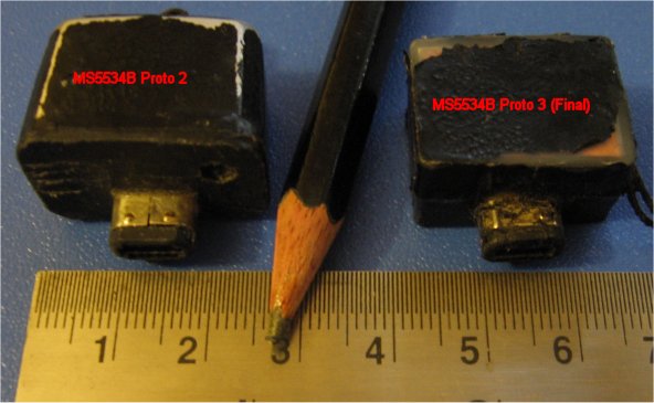
Note that both the MS5534B and SCP1000 have been designed for ultra low-power watch altimeters, not high-speed, high-resolution, low-noise variometers. The MS5534B can be sampled at up to 15 readings/second with a pressure resolution of 10Pa, and a noise figure of +/-40Pa. The SCP1000 can be sampled at up to 9 readings/second with a pressure resolution of 4Pa, and a noise figure of +/-??Pa.
The SCP1000 has a two-wire interface as opposed to the MS5534B 3-wire interface. This allows us to use the remaining two pins on the Gameboy Advance link port for a second port. So we can interface two SCP1000 sensors, giving us 18 interlaced samples/second at 4Pa resolution. This results in a faster responding vario.
In flight, the single MS5534B based vario responds faster than my Renschler Solario audio-only vario, but is not as quick as a Brauniger iQ.
The SCP1000 (core duo) based vario prototype has much faster response. I haven't flown with it yet, this conclusion is based on vario-in-hand-waving arguments.
The pressure sensor uses insignificant power as the sensors are designed for watch based altimeters. The additional battery drain for our application is primarily due to the use of a flash cartridge as opposed to a game ROM. If you're really concerned about battery life, buy a flash cartridge brand that advertises its low-current drain. And turn off the screen backlight as this is useless outdoors in daylight.
Tested battery life with the alti-vario application running in real-time display mode was 11 hours and 30 minutes. This was with a 2 year old GBA SP, ProCard128M flash cartridge, MS5534B sensor dongle, and the backlight switched off.
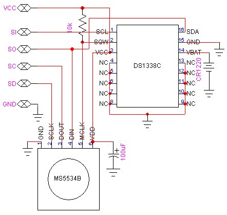
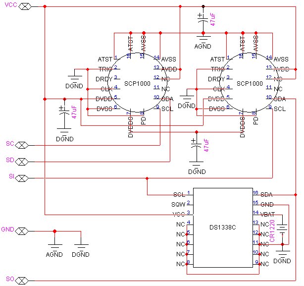
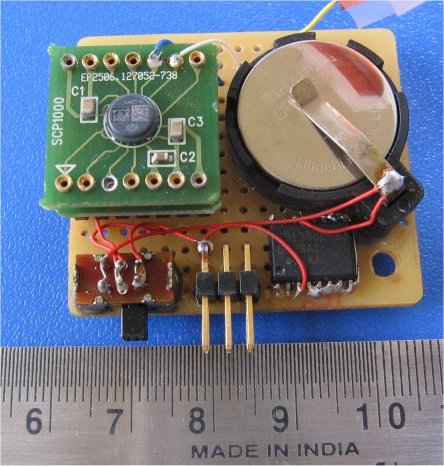
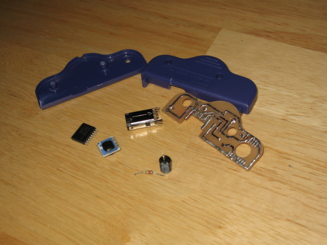
This prototype uses two SCP1000 header boards supplied by VTI, which have 0.47uF and 0.1uF ceramic bypass caps. The 47uF tantalum caps in my schematic are mounted on the bottom of the main board, in parallel with these caps.
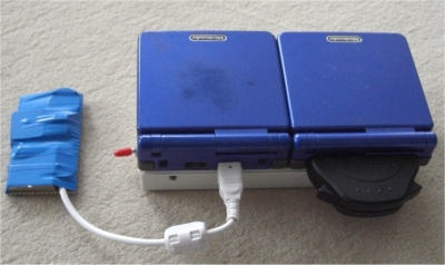
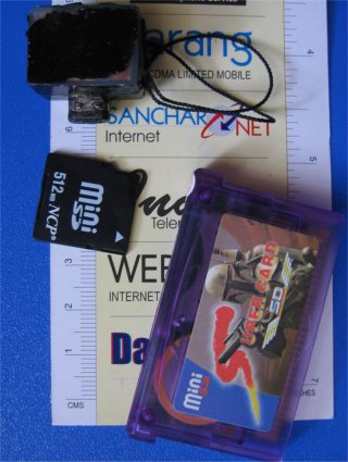
I was experimenting with the use of battery power versus GBA power, thats what the bulky CR2032 battery and switch is for. In practice you can use the much smaller CR1220 battery specified in the schematic as it is only required to power the DS1338 RTC when the sensor dongle is unplugged or the GBA is switched off.
Flash cartridges are sold with a USB linker cable and PC-based software for downloading applications to the cartridge. If the alti-vario code is the only application you load on the cartridge, there's nothing you have to do, the application will start up as soon as you power on. If you have multiple applications downloaded, you'll get a boot menu that allows you to select the application. So you could have lots of games, e-books etc. in addition to your alti-vario. Ideal for extreme parawaiting and hangwaiting.
You can also use a Supercard (www.supercard.cn). This has the form factor of the Gameboy ROM cartridge with a socket for an external SD/miniSD flash card. This is a much cheaper option if you have spare SD cards lying about. I have the miniSD version. People have reported that games run slower on this card and that battery life is lower than with standard flash cartridges. It seems to work OK for the alti-vario. Just make sure you disable all the re-start/game save options that slow it down.
A problem (at least with the Supercard unit I have) is that the battery used for the non-volatile game save data is rechargeable and doesn't seem to hold its charge for more than a couple of days. That means you lose your flight log data if you don't regularly switch on your gameboy ...
Another option is the M3 mini-SD adapter card. This is more expensive but apparently does not suffer from the slow-down or battery issues. Haven't tried it myself though.It also has a built-in real-time-clock, so you could eliminate the external RTC in the dongle if you figure out how to access the RTC from your code.
I am now using the free Visual Studio 2005 Express Edition IDE with the HAM and HEL libs. Check out the instructions for transferring a VisualHAM project to VS2005 elsewhere on this site...
The schematics and datasheets are in the document archive.
The source archive contains the altimeter/vario project for a Visual Studio 2005 development environment using the HAM and HEL libraries.
The source code is written in C++. I am sure it can be easily understood and modified by anyone who knows C. It can be compiled for either the MS5534B or SCP1000 sensors by uncommenting the relevant #define in the def.h file. And hitting the compile button.
The change history is at the bottom of the main.cpp file.
The output binary file that you need to download to the flash cartridge is the *.gba file.
Summary
On power up, a flight log screen displays flight data for past flights. Press the START button to take you to the settings screen. Here you can modify user-settable parameters. Just before launching, press the START button to display real-time altitude, temperature, and climb rate. On landing, press the START button to save the flight data and take you back to the flight log screen.
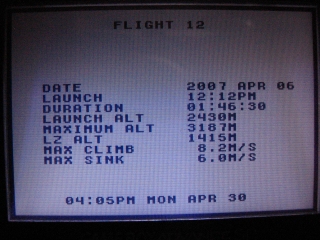
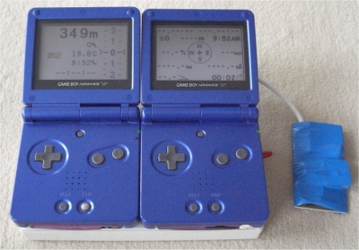
The unit powers up with a flight log screen, where flight data is displayed. If the unit has already recorded 100 flights, the oldest record is overwritten with the current flight record. The snapshot above shows the logged data for an mid-day flight at Billing, India.
A flight data record is created only if the max altitude above take off is more than 5m, or if the difference between take off altitude and end of flight altitude is greater than 5m.
The data fields displayed for each flight are :
The flight log screen displays the most recent flight record first. Use the joypad LEFT and RIGHT buttons to scroll through the list.
Press the SELECT button to delete the currently displayed flight record.
Press the START button to take you to the Settings screen.
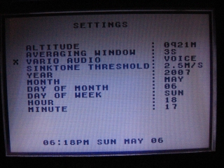
This screen displays real-time altitude data, and several user-settable parameters. Use the joypad UP and DOWN buttons to scroll through the list. When a list item is selected, use the joypad LEFT and RIGHT buttons to select from the available options. All settings are saved to memory.
ALTITUDE
The altimeter/vario uses a barometric pressure sensor that gives us absolute pressure readings. To convert pressure to altitude (in metres) we use the standard model of the lower atmosphere (1976 US Standard Atmosphere) :
To correct the displayed altitude reading, press the LEFT or RIGHT joypad button - this will adjust the internal mean sea level reference pressure Po. The range of equivalent altitude adjustment is approximately +/- 200 metres.
So if you want your absolute altimeter reading to be accurate, calibrate the altimeter before flying by going to a location with known altitude, and adjust the reference pressure to get the display reading as close as possible to the known altitude. This corrected altitude reading is known as QNH pressure altitude.
Press the A button to revert the internal sea level reference pressure Po to the 1976 US Standard Atmosphere model value (101325Pa). The altitude now displayed is known as QNE pressure altitude. This is used for commercial airspace definition.
Note that the real-time display also shows altitude above launch (AL), known as QNF altitude. This information may be of some comfort if you get into cloud.
AVERAGING WINDOW
To estimate climb/sink rate, the software calculates a linear regression of the sensor altitude samples within a sliding time "window". This sensor sample window can be adjusted from 2 seconds to 8 seconds.
Decrease the sample averaging window to get a faster response time. The trade-off is increased jitter due to noise in the samples. Increase the sample averaging window to filter out small climb/sink rate variations and noise. The tradeoff is an increased ramp-up delay to the true climb/sink rate.
Press the LEFT joypad button to decrease the averaging window, the RIGHT joypad button to increase the averaging window.
VARIO AUDIO MODE
Select between a voiced mode and a chirp mode. In voiced mode, a voice calls out the integer climb rate in metres per second, with the pitch proportional to the fractional climb rate.
In chirp mode, the vario will emit a swept frequency chirp for climb and a continuous tone for sink.
THRESHOLD SINKRATE FOR AUDIO WARNING
In Chirp mode, the vario will emit a continuous tone if the sink rate is greater than a threshold value. This continuous tone is a preset low frequency if the sinkrate is greater than a user-defined threshold and less than 4.0 m/s. The tone is a preset high frequency if the sinkrate is greater than 4.0 m/s.
In Voice mode, a voice calls out "Sinking" for the first case, and "Attention" for the second case.
The user-defined threshold sinkrate can be varied from 0.5m/s to 4.0m/s in steps of 0.5m/s. Press the LEFT joypad button to decrease the threshold, the RIGHT button to increase the threshold.
CLOCK SETTINGS
The sensor dongle has a battery backed real-time clock. Year, month, day, day of week, and current time (hours, minutes) can be set here.
From the Settings screen, press the START button to go to the real-time display screen. At this point the unit will record the launch altitude.
The flight data screen displays current altitude above mean sea level (MSL), altitude above launch, temperature, current time, and elapsed flight time in hours, minutes and seconds.
It displays climb/sink rate as a color coded scrolling tape - red numerals for climb, blue numerals for sink.
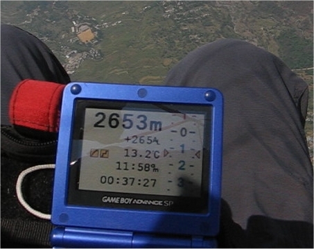
The snapshot above shows the real-time display.
The vario display is clamped to +/-16 m/s, but the flight log will record climb/sink rates of up to +/-50 m/s.
The flight duration timer will start automatically when the altitude above or below take off altitude exceeds 5m.
The right shoulder button toggles the Vario audio mode - selecting between voiced and chirp mode.
VARIO LOWPASS FILTER
A lowpass filter is used to filter out noise in the estimated climbrate. The trade-off is that as you increase the filtering, the ramp-up delay to the true climb/sink rate increases.
Press the B button to select one of three filtering levels - low, medium or high. The left square black and yellow icon on the display shows the selected filtering level.
VARIO CLIMBRATE RESOLUTION (ONLY IN VARIO CHIRP MODE)
In chirp mode, the vario emits chirps with a duration, frequency and repetition rate that depends on the climb rate. The chirp frequency is continuously proportional to climbrate. However, the chirp duration and repetition rate have discrete values for the following ranges : 0m/s - 1m/s, 1m/s - 2m/s, 2m/s - 4m/s, > 4m/s. For low climb rates there is a longer interval between chirps.
If the climbrate changes by more than a user-selectable step size the vario will immediately respond with a new chirp without waiting for the chirp repetition interval to elapse. If the climbrate remains the same or does not change by more than the selected step size, the vario will emit a new chirp only after the chirp repetition interval elapses.
So if you are flying in light lift and would like the vario to respond immediately to small changes in lift, use a small step size.
Press the A button to select one of three step sizes - large, medium or small. The right square black and yellow icon on the display shows the selected step size.
If a nervous vario bugs you, set the vario climbrate resolution to large step size, set the vario filtering to maximum and use a bigger averaging window.
End of Flight
On landing, press the START button. This will stop the flight duration timer, record the LZ altitude and if the flight altitude thresholds are met, a flight data record is saved. The display then reverts to the Flight Log screen with the first record showing the data for the just completed flight.
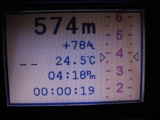
When the simulation starts, the altitude is initialized to 500m MSL and the temperature to 25.0 Celsius. The display altitude, altitude above launch, temperature, and flight duration are all simulated based on elapsed time and the accumulated change in altitude. The temperature change assumes a lapse rate of 6.5 Celsius per 1000m.
The right shoulder button toggles the Vario audio mode - selecting between voiced and chirp mode.
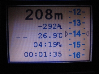
Note that the background in simulation mode is now yellow, to differentiate it from the real-time display mode with a white background - just in case you inadvertently launch with the unit in simulation mode. Additionally, the two icons for the Vario Filter and Vario Discrimination selection are replaced with "-" markers.
The following screen snapshot shows a climb rate of 3.75 m/s in vario simulation mode.
The next screen snapshot shows a sink rate of 14 m/s in vario simulation mode.
Press the START button in Vario Simulation mode to exit to the Flight Log Screen.
GBA Button -> PC Keyboard Equivalent
Start -> Enter
Select -> Backspace
A -> Z
B -> X
Left Shoulder -> A
Right Shoulder -> S
Joypad Up -> Up arrow
Joypad Down -> Down arrow
Joypad Left -> Left arrow
Joypad Right -> Right arrow
Try out the vario simulation mode to see the scrolling variometer and hear the audio chirps...
Yuriy Kozhynov (yuriy at kozhynov dot com) has done a professional job of the sensor dongle - here's a snap of his PCB and assembled unit. The new simulation mode, and display of negative altitudes (below sea level) are also due to his input.
The PCB schematics and more snaps can be downloaded here.
Udo (dg9fdu at web dot de) has built and flight tested both the vario and the gps, using an external power pack - real neat job. He sent me a few snaps of his set up ...