The vario will automatically go to sleep to conserve battery life if it does not detect significant vertical movement for more than 15 minutes. To recover from sleep state, simply switch off and on again.
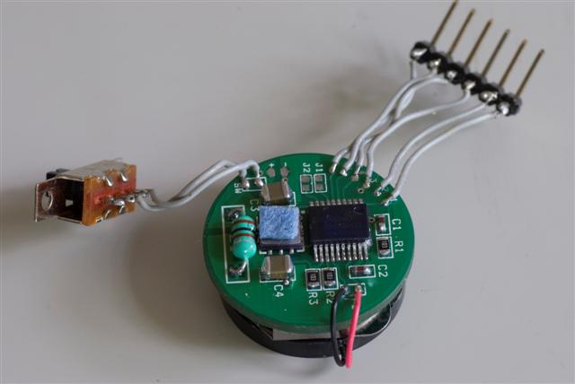
The analog comparator in this PIC24 micro-controller version is used to drive the piezo transducer in push-pull mode, resulting in reasonable audio volume even with the low driving voltage.
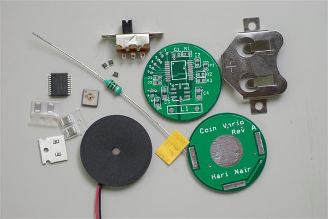
The ferrite isolators L1 and L2 are used to isolate the BMP085 analog power supply and ground from the switching digital noise of the main circuit. This is an improvement over the Rev A circuit which only had isolation of the VDDA supply.
The 10k I2C pullup resistors for the BMP085 are the maximum value specified in the datasheet. This is to minimize the switching current in operational mode.
The circuit draws a current of about 720uA at 3V, with the PIC24 MCU running off the internal LPFRC oscillator at an effective instruction clock of 250kHz.
In sleep mode, the current drain is around 10uA. To minimize the sleep current, you must use good quality ceramic SMD caps and make sure there is no solder flux residue creating leakage paths. Of course, if you switch off the vario manually, no current is drawn from the battery at all.
CR2032 batteries are rated at about 220mAHr for a continous discharge rate of 0.4mA, with end-of-life voltage 2V. Even if the specified capacity is degraded because we are operating with a continuous current of 0.7mA, we can expect 100+ hours run-time.
The pads 1...6 are used to flash and debug the microcontroller using the Microchip PicKit2 programmer interface.
If jumper J1 is open, climb beep frequency and repeat rate are proportional to vertical speed. If J1 is shorted, the climb beep frequency is proportional to vertical speed, and the beep repeat rate is proportional to the acceleration.
If jumper J2 is open, the vario filter damping is fixed. If J2 is shorted, the vario filter damping is varied based on vertical speed and acceleration to try to minimize the response delay without increasing the noise too much.
Most piezo transducers are designed to operate at a fixed resonant frequency. This is fine if you just want a alarm tone. However, we need to generate a range of frequencies from a few hundred Hertz to a few kiloHertz. The Kingstate KPEG006 is one broad-band piezo transducer that works well. I have also had similar results with a side-firing 1" square cellphone piezo speaker that I sourced at Electronic Goldmine, and a piezo wafer+diaphragm salvaged from a cheap automobile audio tweeter.
You can submit the .brd file to OSHPark for cheap high-quality PCBs. PCBs.io offer a similar service but I have not tried them yet.
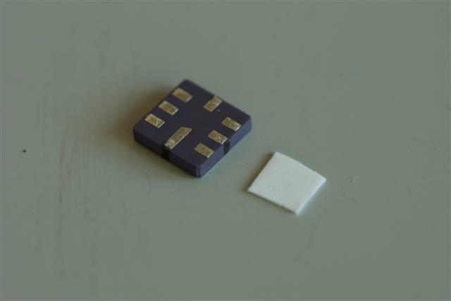
I pre-tinned the BMP085 pads and the pcb footprint with 63/37 solder. Left approximately 1/2 mm solder bumps on the BMP085 pads, and leveled the pcb footprint (desoldering braid can be useful here). You'll have trouble trying to place the BMP085 aligned to the footprint if both the pads and footprints have solder bumps.
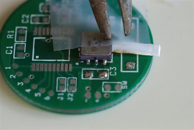
I then cleaned both the pads and footprint with alcohol, then applied flux to both with a Kester "no-clean" flux pen. "No-clean" emphasizes that any flux residue will be non-corrosive and non-conductive - you won't be able to get under the BMP085 later ! I marked the center pin on each side of the BMP085 with a black marker to help align the part on the footprint.
63/37 solder is a eutectic alloy. A eutectic alloy melts at a well-defined low temperature (in this case ~183Celsius) rather than over a range of temperatures. So its easy to see when the reflow happens. Shine a bright light on the board. When the solder melts, it will suddenly turn from dull to shiny, and the component will "settle". Rap the pan with the edge of a knife a few seconds later. The component will automatically align itself with the footprint with the magic of liquid surface tension.Turn off the heat, and you're done. 100% success rate in 3 reflow trials.
Of course if you have a solder stencil and solder paste, you could do the whole board in one shot. I reserved the "reflow soldering" only for the BMP085.
 <
<