Includes gerber files for a pcb that can be ordered inexpensively from sources like BatchPCB.com, and full source code.
With the faster sampling rate and good pressure resolution, this looks really good - lots of bang for the buck.
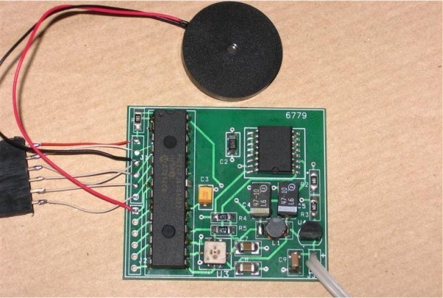
The Kingsgate KPEG006 piezo buzzer is connected to J2.1.
The Nokia 3310LCD mounts directly to the back of the pcb. You need to apply
a little pressure to ensure the LCD glass-spring contact is good.
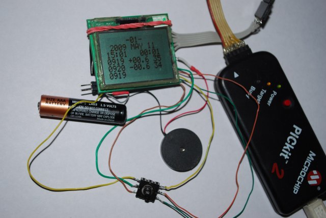
I used the KFC314 5-way joystick from www.techtoys.com.hk for the buttons. You can use 5 separate
push-buttons connected to J2.2 - J2.6 with a common ground.
Using a single AA/AAA battery as power source
The circuit uses a 3V LDO linear regulator. You can use a 3.7V Lithium Poly battery. I also found that a 1.5V AA or AAA battery stepped up to 3.3V using a MAX1678 DC-DC converter works quite well, as an input to the linear regulator. The vario circuit draws only 5mA at 3V with the MCU running at 2MHz internal clock. The DC-DC converter switching noise is therefore low and is filtered by the linear regulator, so it does not increase the sensor sampling noise.
With a MAX1678 converter, the best conversion efficiency I have achieved is approximately 75%. This really depends on the quality of the capacitors and inductor in the converter circuit. The lower the ESR of the capacitors and DCR of the inductor, the higher the efficiency. Electrolytic caps are no good - the best results are with SMD ceramic or tantalum caps specifically meant for DC-DC converter applications. You can reduce the ESR of standard ceramic/tantalum caps by using two or three in parallel.
With an AAA alkaline battery and MAX1678 converter, estimated run-time is 50+ hours.
Increasing the audio volume
The mcu drives the piezo speaker with a 0-3V square wave - thats 3Vp-p. The KPEG006 datasheet specs a 10Vp-p swing for the component. I found the volume is just about OK for my requirements - I have an open-face bicycle helmet and the vario is on a front container.
If the volume isn't enough for you, the easiest solution is to add another piezo in parallel. They present a capacitive load and at the low frequencies we use, the impedance isn't low enough to be a problem.
Another option is to use a MAX3226 TTL-RS232 converter to drive the piezo speaker. This component will work off a 3V power supply and a 0-3V swing on the TX line will result in a 5V to -5V swing on the output line, thats 10Vp-p, so it almost looks like it was made to order for our purpose.
The only issue is that piezos should not be left with a DC potential across the wafer. The solution is to use an extra gpio pin on the mcu to supply the VCC voltage for the MAX3226. The VCC pin is powered a few instructions before the audio square wave generation, to allow the MAX3226 to settle. The VCC pin is cleared when the beep completes.
This works very well with PIC24 micros - they can source and sink ~20mA. The MAX3226 requires very little current, but even so, an 8051 micro does not really have any current sourcing capability on the i/o pins. With an 8051, you could maybe try a 1K pullup resistor on the gpio pin.
Just make sure you keep the MAX3226 well away from the pressure sensor, and bring the MAX3226 ground pin and piezo ground back to the 3V regulator ground with a separate wire or pcb track. This is to avoid adding more sensor sampling noise due to the charge pump operation of the TTL-RS232 converter.