The circuit draws less than 0.5 mA from the storage capacitor "battery" when running. Run-time once fully charged is more than an hour in complete darkness. If exposed to outdoor daytime light conditions, it remains charged, as the solar cell charging current is much higher than the current drawn by the circuit.
Power is retained in the storage capacitor when switched off.
The lowest usable circuit voltage is limited by the MS5534B specifications - minimum VDD is 2.4V. We use a low drop-out 2.5V linear regulator (MAX8510) - it only needs about 40uA in the ground pin to operate, and the drop out voltage is less than 150mV. The total current draw of the circuit is around 300uA when running.
The 6V open-circuit / 16mA short-circuit solar cells are available for US$1.50 each from Futurlec (futurlec.com). The Goldcap 1Farad capacitor (from AAAA-Electronic) has a maximum voltage rating of 5.5V. The 0.6V voltage drop of a generic silicon diode (IN4001) ensures the maximum charging voltage is less than 5.5V. The diode also prevents reverse current into the solar cell from the charged capacitor in dark conditions.
To charge the Goldcap from a 5V USB port, we only need to limit the current for the case when the capacitor is completely drained (0V). USB ports are designed for a maximum current draw of 0.5A. A Schottky diode (this has a lower forward voltage drop, about 0.3V) protects the USB port against reverse voltage. The internal series resistance of the Goldcap is a few tens of ohms. An additional series resistance of 22 ohms is sufficient to allow the Goldcap to charge to 4V in 30seconds.
The exponential charging curve means that it takes much longer to approach the charging voltage of 4.7V (5V minus 0.3V), but a minute of charging is more than enough if you are planning to go flying at sunset and did not get a chance to get the vario out in the sun earlier.
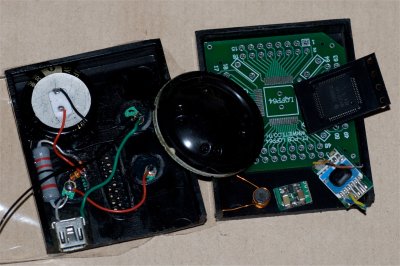
I used a 64LQFP breakout board (also from Futurlec) for the MSP430 micro. You'll need a fine-tipped soldering iron, a desoldering wick, "no-clean" flux and lots of patience to solder the micro on to the break out board. Make sure you clean it well, check for shorts and bad solder connections with a magnifying loupe. Take your time to get it right ... But after that the circuit assembly is relatively easy!
TI MSP430 microcontrollers are known for their low power consumption. Note that this audio vario application only uses around 8kbyte of code space, so the MSP430F1491 with its 60Kbyte flash is overkill. A cheaper version with 16kbyte flash and an easier to solder package would be more appropriate.
For the audio output, I salvaged the piezo diaphragm from a cheap tweeter (I got a pair for about 1US$) meant for automobile installation. This piezo works quite well with a usable frequency range from 400Hz till well above 10kHz.
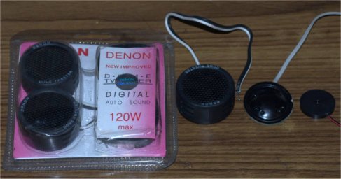
The piezo is driven by two out-of-phase square-wave PWM outputs from the MSP430. This reversal of polarity each half-cycle results in the transducer surface being pushed forwards AND backwards from rest, doubling the volume of air moved per cycle, and therefore increasing the volume.
This trick is necessary because of the low single-ended drive voltage (only 2.5V).
When the vario is switched on, charge status is indicated by a series of beeps. The actual voltage is first rounded up to the nearest volt, and it outputs one beep per volt. So a capacitor voltage anywhere between 3.5V and 4.4V would be indicated by 4 beeps. After this, the vario goes into normal operating mode. Sink greater than -3m/s is indicated by a continuous tone. Climb is indicated by chirps whose frequency and repetition rate increase as the climbrate increases, upto a limit of +10m/s.
The internal ADC used to convert the capacitor voltage uses VCC (2.5V) as reference. We therefore need the potential divider resistors R2 and R3 to get a scaled capacitor voltage less than 2.5V. These values (220K and 330K) are an order of magnitude larger than optimal for the ADC, but for this application we are more concerned about battery drain than accurate voltage readings.
There are options in the source code for a constant frequency "beep" or swept frequency "chirp", and for discriminating both vertical speed and acceleration, or only vertical speed. For the speed and acceleration option, the beep/chirp base frequency depends on the climbrate, while the repetition interval depends on the magnitude of the acceleration (a French pilot Antoine Lomberty suggested this feature). For the speed option, both beep/chirp base frequency and repetition interval depend on the climbrate.
These options can be compiled into the code, or enabled/disabled at runtime via DIP switch/jumpers, depending on a couple of #defines. The archived source code uses the compiled version - it is set for the speed and chirp options.
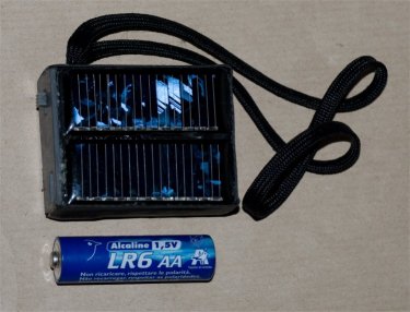
The vario is light and compact. It can be velcroed onto helmet, shoulder strap or front deck, anywhere obviously not blocked from the sun.
In the picture above, the AA battery is shown as a scale reference.
Sensitivity is good, better than my Renschler Solario. And the chirping audio is quite pleasant.
Note that in the simplified circuit above the MSP430 microcontroller target and the programming adapter must be powered by a 3V - 3.3V supply for programming.